
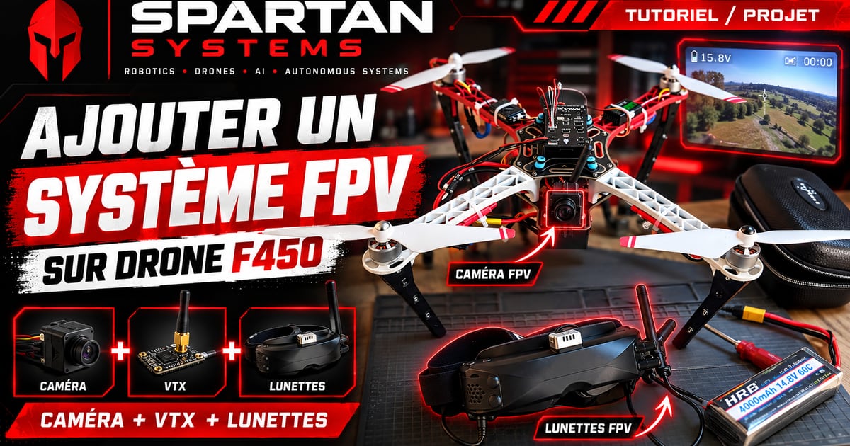
Fitting an F450 drone with an FPV camera lets you receive its live feed in compatible goggles or on a monitor. In this tutorial, we’ll install the camera and its video transmitter, also called a VTX, wire everything up and mount the setup on the frame.
This tutorial follows on from the guide Building a DJI F450 Drone, which covers frame assembly, the flight controller and the first flight.
Displaying telemetry data with an OSD module will be covered in an upcoming article and a dedicated video. Here, the camera is connected directly to the VTX.
What you’ll need
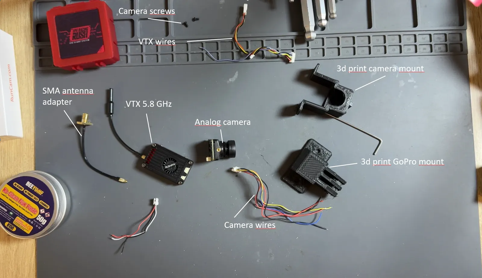
- A RunCam FPV camera.
- A 5.8 GHz video transmitter: the Rush FPV Max Solo used in this build.
- A compatible antenna and, if needed, an MMCX to SMA adapter.
- A 3D-printable camera mount.
- A GoPro mount (optional).
- M3 screws and nuts, plus cable ties.
- A soldering iron, solder, soldering flux and heat-shrink tubing.
- Wire cutters and wire strippers.
- FPV goggles or a monitor compatible with the video transmission used.
Wiring diagram
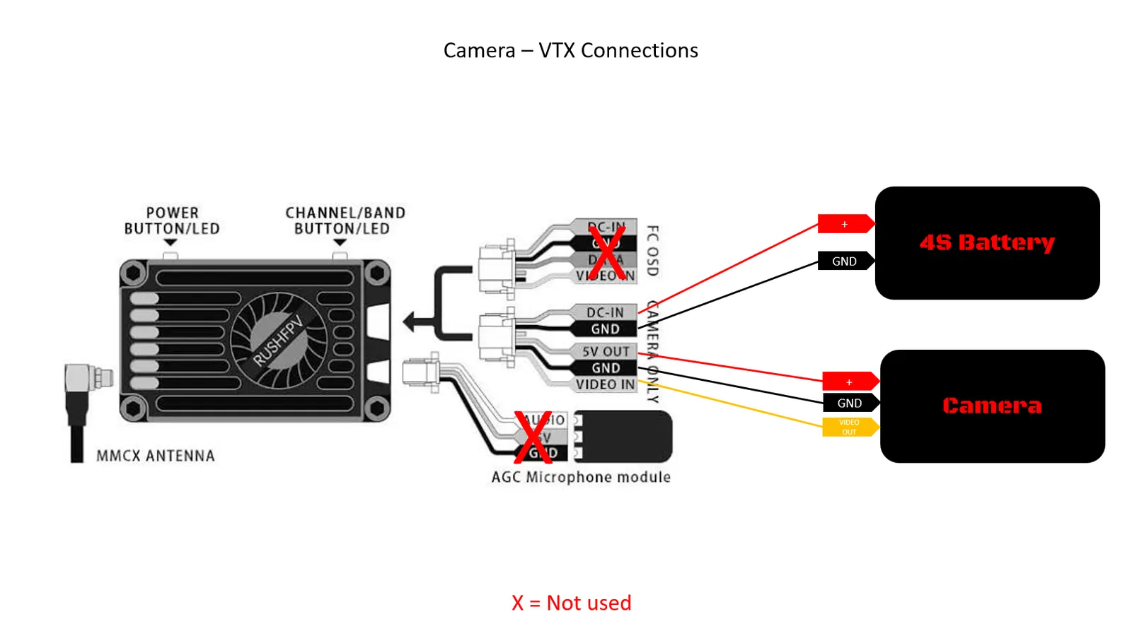
The build relies on three connections: powering the VTX from the drone, powering the camera from the VTX, and sending the camera’s video signal to the VTX.
The full build on video
To go along with this tutorial, watch the full assembly video and follow the build step by step.
1. Identify the connections
Identify the wires and connector pins on the camera and the VTX before you start.
The table below lists the connections used in this build:
| From | To | Wire color |
|---|---|---|
| Drone power: positive (+) | VTX: DC IN power input | Red |
| Drone power: ground (GND) | VTX: GND | Black |
| VTX: 5 V power output | Camera: VIN power input | Red |
| VTX: GND | Camera: GND | Black |
| Camera: VIDEO OUT | VTX: VIDEO IN | Yellow |
Check your components’ markings before soldering: wire colors alone are not enough to identify a connection. Also make sure the camera accepts 5 V and that the drone’s supply voltage is compatible with the VTX input.
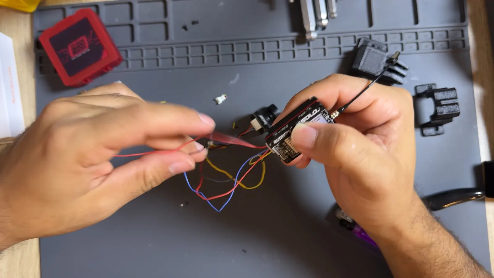
2. Solder the camera and VTX wires
Do all the wiring with the battery disconnected.
Cut the wires to the required length, leaving enough slack to mount the components on the frame. Then strip their ends.
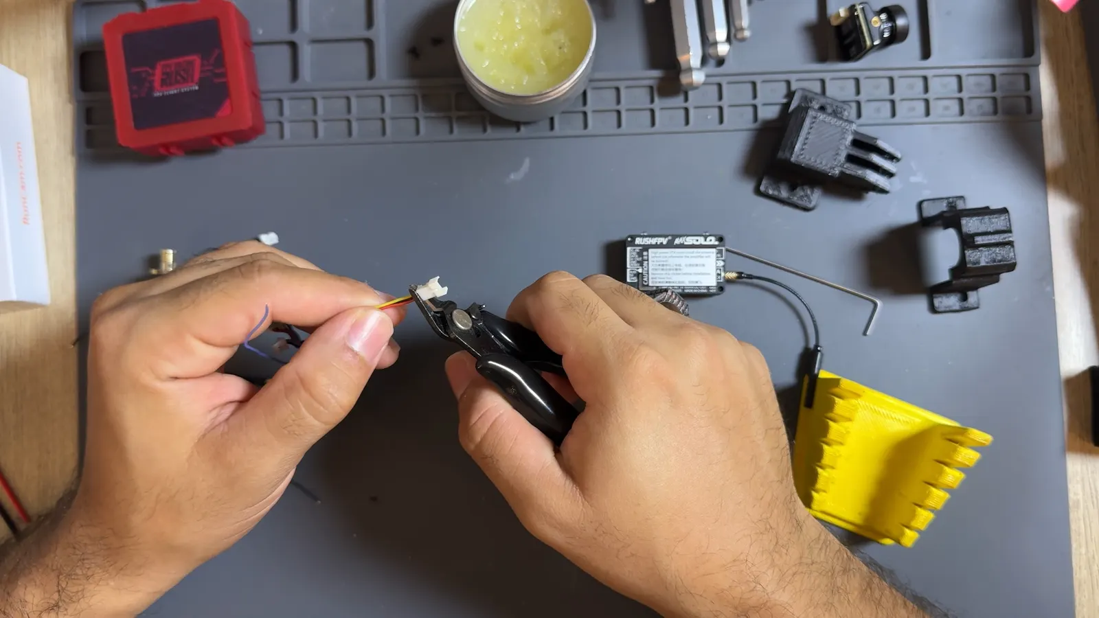
Before soldering, slide a piece of heat-shrink tubing onto each wire you’re joining. The tubing will insulate the joints and prevent short circuits.
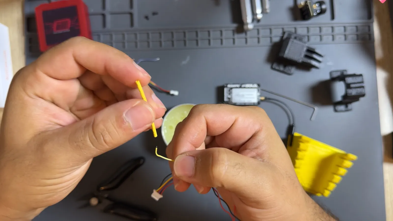
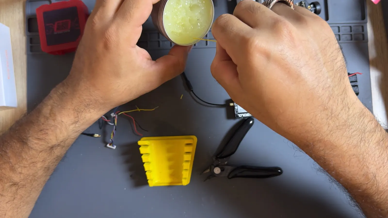
Apply a little flux to the stripped ends to make soldering easier.
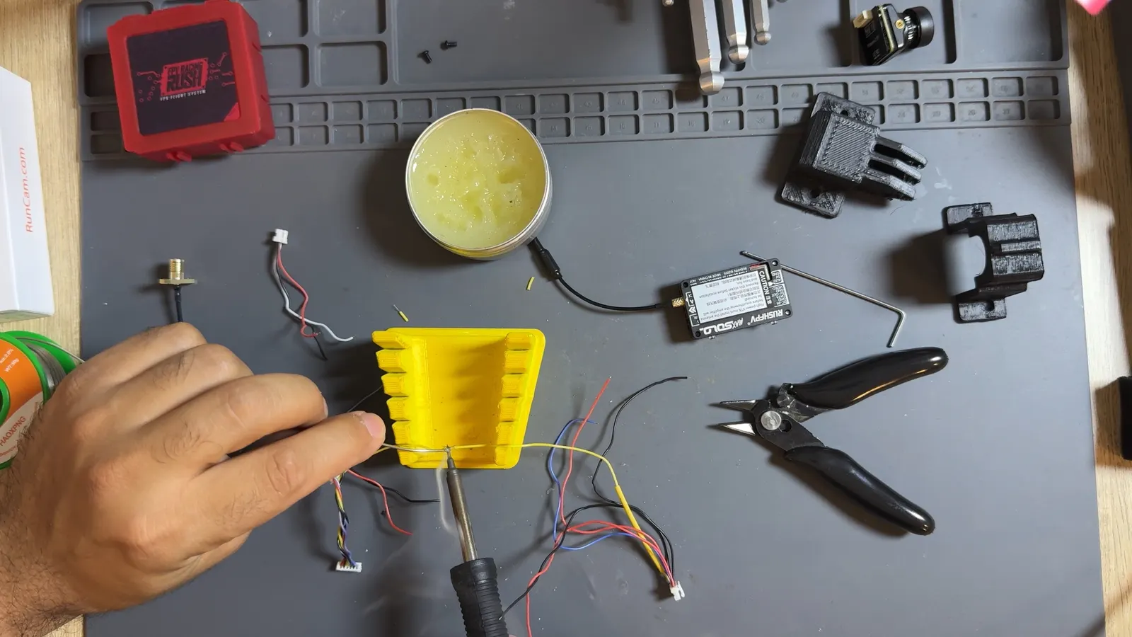
Solder the wires together following the wiring diagram and the connection table.
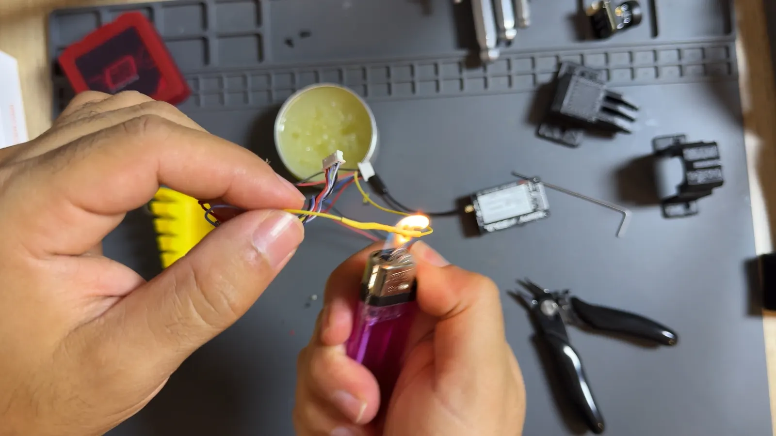
Once the joints have cooled, cover them with the heat-shrink tubing. Heat the tubing so it shrinks tightly around each joint.
Then plug the connectors into the camera and the VTX.
3. Connect the VTX power supply
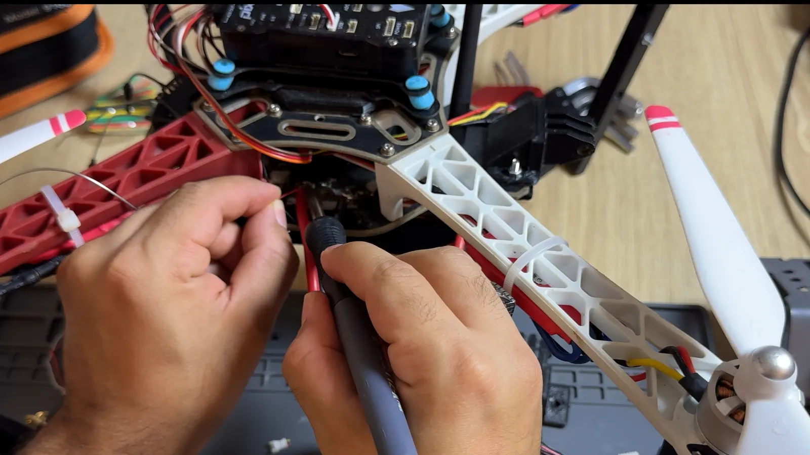
Solder the VTX’s positive (+) and ground (GND) wires to the matching power pads on the F450. If your drone uses a separate power distribution board, make these connections on that board.
Respect the polarity and check that no solder joint accidentally bridges positive and ground.
4. Mount the camera on the frame
Install the camera in its mount using the screws supplied with it.
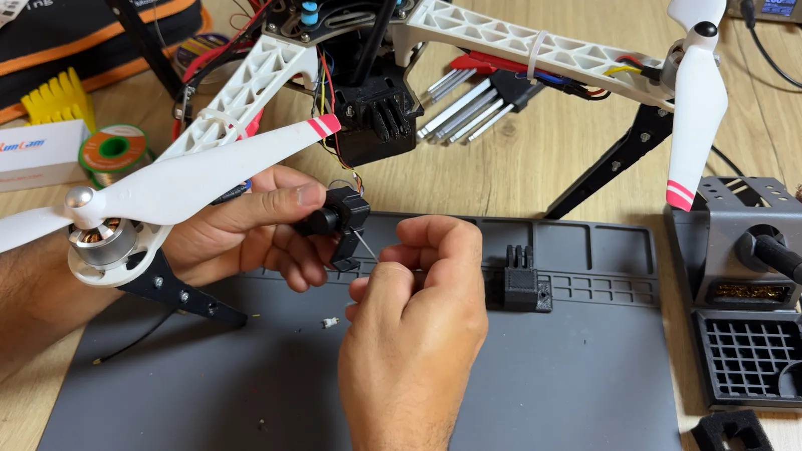
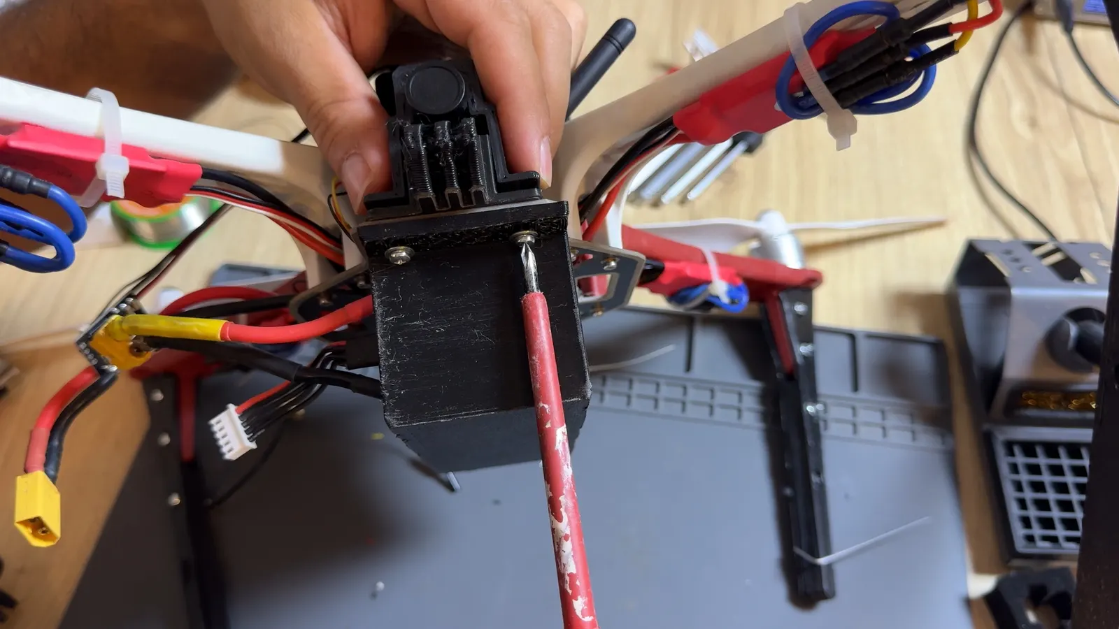
Then attach the camera mount to the frame with M3 screws and nuts. If you’re also using a GoPro mount, install it at this stage.
5. Install the VTX and its antenna
Connect the antenna to the VTX. For this build, I used an MMCX to SMA adapter.
Then secure the VTX and the antenna to the frame with cable ties. Keep the cables well away from the propellers and leave room for air to flow around the VTX.
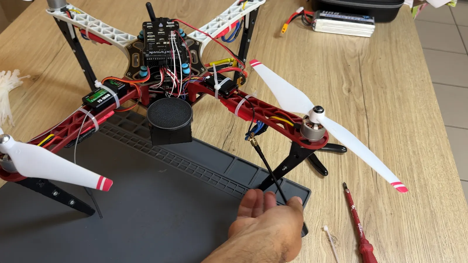
6. Check the video link
Before the first test, remove the propellers and check the connections, the insulation of the solder joints and how securely the components are mounted. Make sure the antenna is connected to the VTX before powering it on.
Plug in the drone’s battery, then switch on your FPV goggles or monitor. Set the receiver to the same band and channel as the VTX to receive the camera feed.
If no image appears, first check that the camera and the VTX are powered. Then check the video wiring and that the transmitter and receiver are on the same channel. If needed, change the VTX channel using its button, following the procedure in its manual, then adjust the receiver.
Once you have an image, adjust the camera tilt to get the framing you want. Your F450 now has an onboard video feed!